0%

Linux驱动之ALSA(三)编解码器类驱动实例

这里以Wolfson公司的编解码芯片WM8960为例来说明上篇介绍的相关内容。

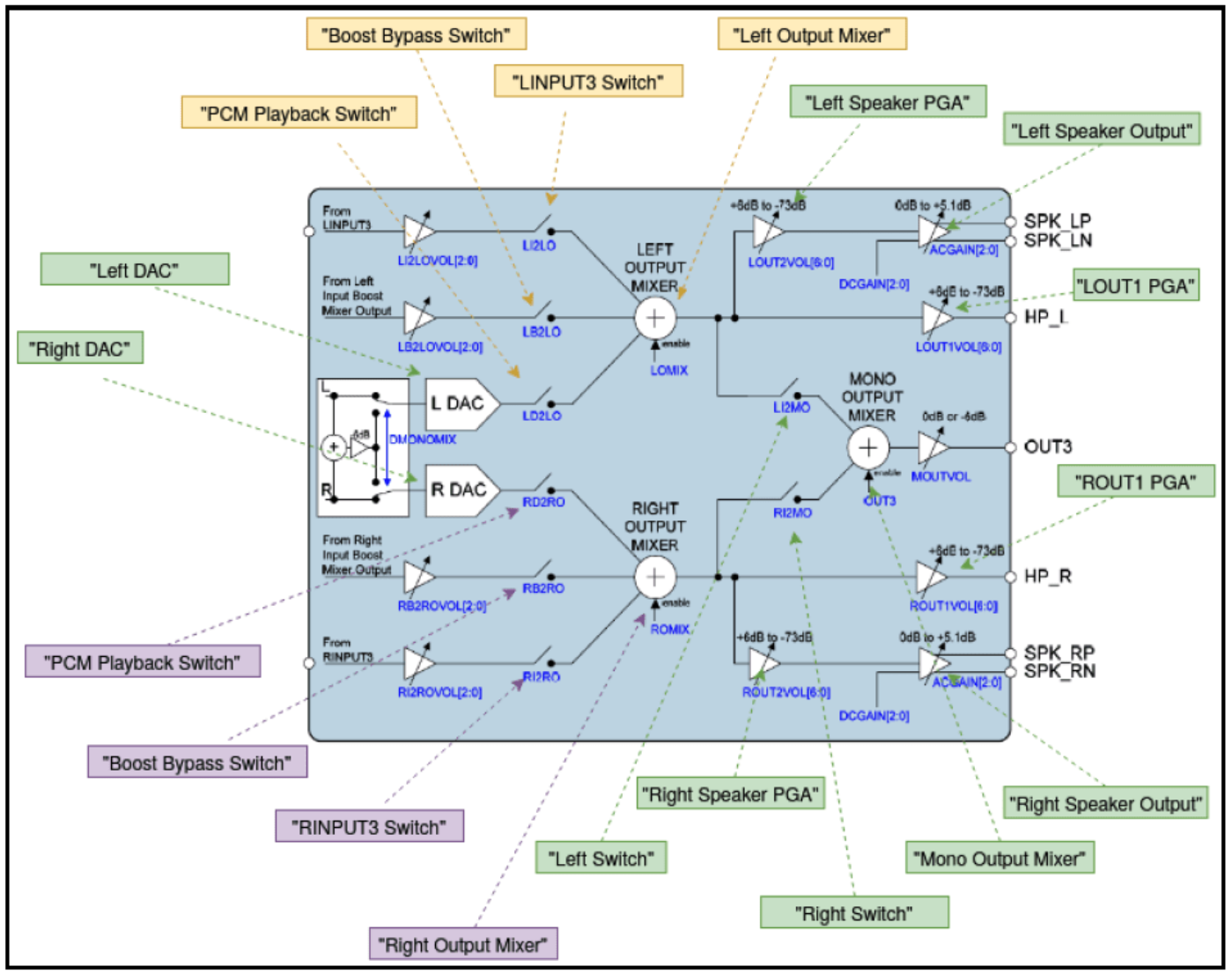
定义widget所需的DAPM Kcontrol

1
2
3
4
5
6
7
8
9
10
11
12
13
14
static const struct snd_kcontrol_new wm8960_loutput_mixer[] = {
SOC_DAPM_SINGLE("PCM Playback Switch", WM8960_LOUTMIX, 8, 1, 0),
SOC_DAPM_SINGLE("LINPUT3 Switch", WM8960_LOUTMIX, 7, 1, 0),
SOC_DAPM_SINGLE("Boost Bypass Switch", WM8960_BYPASS1, 7, 1, 0),
};
static const struct snd_kcontrol_new wm8960_routput_mixer[] = {
SOC_DAPM_SINGLE("PCM Playback Switch", WM8960_ROUTMIX, 8, 1, 0),
SOC_DAPM_SINGLE("RINPUT3 Switch", WM8960_ROUTMIX, 7, 1, 0),
SOC_DAPM_SINGLE("Boost Bypass Switch", WM8960_BYPASS2, 7, 1, 0),
};
static const struct snd_kcontrol_new wm8960_mono_out[] = {
SOC_DAPM_SINGLE("Left Switch", WM8960_MONOMIX1, 7, 1, 0),
SOC_DAPM_SINGLE("Right Switch", WM8960_MONOMIX2, 7, 1, 0),
};

在上述代码中定义了左右输出通道的混音器控件,以及单声道输出混音器:wm8960_loutput_mixer、wm8960_routput_mixer、wm8960_mono_out。

定义真实的widget,包括DAMP控件

1
2
3
4
5
6
7
8
9
10
11
12
13
14
15
16
17
18
19
20
21
22
23
24
25
26
27
28
29
30
31
32
33
34
35
36
37
38
39
40
41
42
43
44
45
46
47
48
49
50
static const struct snd_soc_dapm_widget wm8960_dapm_widgets[] = {
SND_SOC_DAPM_INPUT("LINPUT1"),
SND_SOC_DAPM_INPUT("RINPUT1"),
SND_SOC_DAPM_INPUT("LINPUT2"),
SND_SOC_DAPM_INPUT("RINPUT2"),
SND_SOC_DAPM_INPUT("LINPUT3"),
SND_SOC_DAPM_INPUT("RINPUT3"),

SND_SOC_DAPM_SUPPLY("MICB", WM8960_POWER1, 1, 0, NULL, 0),

SND_SOC_DAPM_MIXER("Left Boost Mixer", WM8960_POWER1, 5, 0,
wm8960_lin_boost, ARRAY_SIZE(wm8960_lin_boost)),
SND_SOC_DAPM_MIXER("Right Boost Mixer", WM8960_POWER1, 4, 0,
wm8960_rin_boost, ARRAY_SIZE(wm8960_rin_boost)),

SND_SOC_DAPM_MIXER("Left Input Mixer", WM8960_POWER3, 5, 0,
wm8960_lin, ARRAY_SIZE(wm8960_lin)),
SND_SOC_DAPM_MIXER("Right Input Mixer", WM8960_POWER3, 4, 0,
wm8960_rin, ARRAY_SIZE(wm8960_rin)),

SND_SOC_DAPM_ADC("Left ADC", "Capture", WM8960_POWER1, 3, 0),
SND_SOC_DAPM_ADC("Right ADC", "Capture", WM8960_POWER1, 2, 0),

SND_SOC_DAPM_DAC("Left DAC", "Playback", WM8960_POWER2, 8, 0),
SND_SOC_DAPM_DAC("Right DAC", "Playback", WM8960_POWER2, 7, 0),

SND_SOC_DAPM_MIXER("Left Output Mixer", WM8960_POWER3, 3, 0,
&wm8960_loutput_mixer[0],
ARRAY_SIZE(wm8960_loutput_mixer)),
SND_SOC_DAPM_MIXER("Right Output Mixer", WM8960_POWER3, 2, 0,
&wm8960_routput_mixer[0],
ARRAY_SIZE(wm8960_routput_mixer)),

SND_SOC_DAPM_PGA("LOUT1 PGA", WM8960_POWER2, 6, 0, NULL, 0),
SND_SOC_DAPM_PGA("ROUT1 PGA", WM8960_POWER2, 5, 0, NULL, 0),

SND_SOC_DAPM_PGA("Left Speaker PGA", WM8960_POWER2, 4, 0, NULL, 0),
SND_SOC_DAPM_PGA("Right Speaker PGA", WM8960_POWER2, 3, 0, NULL, 0),

SND_SOC_DAPM_PGA("Right Speaker Output", WM8960_CLASSD1, 7, 0, NULL, 0),
SND_SOC_DAPM_PGA("Left Speaker Output", WM8960_CLASSD1, 6, 0, NULL, 0),

SND_SOC_DAPM_OUTPUT("SPK_LP"),
SND_SOC_DAPM_OUTPUT("SPK_LN"),
SND_SOC_DAPM_OUTPUT("HP_L"),
SND_SOC_DAPM_OUTPUT("HP_R"),
SND_SOC_DAPM_OUTPUT("SPK_RP"),
SND_SOC_DAPM_OUTPUT("SPK_RN"),
SND_SOC_DAPM_OUTPUT("OUT3"),
};

在这一步中为左右声道选择器定义了一个MUX widget,他们是Left Output Mixer、Right Output Mixer和Mono Output Mixer。 我们还为每个扬声器定义了一个混音器widget:SPK_LP、SPK_LN、HP_L、HP_R、SPK_RP、SPK_RN、OUT3。具体的混音器控制由wm8960_loutput_mixer、wm8960_routput_mixer、wm8960_mono_out来完成,这三个widget都具有power属性,因此,当这些widget中的一个或多个位于一个有效的音频路径时,DAPM框架可以通过其各自的寄存器的第7和第8位来控制电源状态。

定义widget的连接路径

1
2
3
4
5
6
7
8
9
10
11
12
13
14
15
16
17
18
19
20
21
22
23
24
25
26
27
28
29
30
31
32
33
34
35
36
37
38
39
40
41
42
43
44
45
46
47
48
49
50
51
52
53
static const struct snd_soc_dapm_route audio_paths[] = {
{ "Left Boost Mixer", "LINPUT1 Switch", "LINPUT1" },
{ "Left Boost Mixer", "LINPUT2 Switch", "LINPUT2" },
{ "Left Boost Mixer", "LINPUT3 Switch", "LINPUT3" },

{ "Left Input Mixer", "Boost Switch", "Left Boost Mixer" },
{ "Left Input Mixer", "Boost Switch", "LINPUT1" }, /* Really Boost Switch */
{ "Left Input Mixer", NULL, "LINPUT2" },
{ "Left Input Mixer", NULL, "LINPUT3" },

{ "Right Boost Mixer", "RINPUT1 Switch", "RINPUT1" },
{ "Right Boost Mixer", "RINPUT2 Switch", "RINPUT2" },
{ "Right Boost Mixer", "RINPUT3 Switch", "RINPUT3" },

{ "Right Input Mixer", "Boost Switch", "Right Boost Mixer" },
{ "Right Input Mixer", "Boost Switch", "RINPUT1" }, /* Really Boost Switch */
{ "Right Input Mixer", NULL, "RINPUT2" },
{ "Right Input Mixer", NULL, "RINPUT3" },

{ "Left ADC", NULL, "Left Input Mixer" },
{ "Right ADC", NULL, "Right Input Mixer" },

{ "Left Output Mixer", "LINPUT3 Switch", "LINPUT3" },
{ "Left Output Mixer", "Boost Bypass Switch", "Left Boost Mixer" },
{ "Left Output Mixer", "PCM Playback Switch", "Left DAC" },

{ "Right Output Mixer", "RINPUT3 Switch", "RINPUT3" },
{ "Right Output Mixer", "Boost Bypass Switch", "Right Boost Mixer" },
{ "Right Output Mixer", "PCM Playback Switch", "Right DAC" },

{ "LOUT1 PGA", NULL, "Left Output Mixer" },
{ "ROUT1 PGA", NULL, "Right Output Mixer" },

{ "HP_L", NULL, "LOUT1 PGA" },
{ "HP_R", NULL, "ROUT1 PGA" },

{ "Left Speaker PGA", NULL, "Left Output Mixer" },
{ "Right Speaker PGA", NULL, "Right Output Mixer" },

{ "Left Speaker Output", NULL, "Left Speaker PGA" },
{ "Right Speaker Output", NULL, "Right Speaker PGA" },

{ "SPK_LN", NULL, "Left Speaker Output" },
{ "SPK_LP", NULL, "Left Speaker Output" },
{ "SPK_RN", NULL, "Right Speaker Output" },
{ "SPK_RP", NULL, "Right Speaker Output" },
};
static const struct snd_soc_dapm_route audio_paths_out3[] = {
{ "Mono Output Mixer", "Left Switch", "Left Output Mixer" },
{ "Mono Output Mixer", "Right Switch", "Right Output Mixer" },

{ "OUT3", NULL, "Mono Output Mixer", }
};

通过这一步的定义我们知道Left output Mux和Right output Mux有三个输入引脚,分别是Boost Bypass Switch、LINPUT3 Switch、PCM Playback Switch。Mono Output Mixer只有两个输入引脚,Left Switch、Right Switch,所以,上述定义的含义如下:

  • Left Boost Mixer通过Boost Bypass Switch连接到Left Output Mixer
  • Left DAC通过PCM Playback Switch连接到Left Output Mixer
  • LINPUT3通过LINPUT3 Switch连接到Left Output Mixer
  • Left Output Mixer连接到LOUT1 PGA,但是此链接没有开关控制
  • Right xxx同理这里不一一列举出来了

在编解码器驱动程序的probe回调函数中注册widget和路径

1
2
3
4
5
6
7
8
9
10
11
12
13
14
15
16
17
18
19
20
21
22
23
24
25
26
27
28
29
30
31
32
33
34
35
36
37
38
39
40
41
42
43
44
45
46
47
48
49
50
51
52
53
static int wm8960_add_widgets(struct snd_soc_component *component)
{
struct wm8960_priv *wm8960 = snd_soc_component_get_drvdata(component);
struct wm8960_data *pdata = &wm8960->pdata;
struct snd_soc_dapm_context *dapm = snd_soc_component_get_dapm(component);
struct snd_soc_dapm_widget *w;

snd_soc_dapm_new_controls(dapm, wm8960_dapm_widgets,
ARRAY_SIZE(wm8960_dapm_widgets));

snd_soc_dapm_add_routes(dapm, audio_paths, ARRAY_SIZE(audio_paths));

/* In capless mode OUT3 is used to provide VMID for the
* headphone outputs, otherwise it is used as a mono mixer.
*/
if (pdata && pdata->capless) {
snd_soc_dapm_new_controls(dapm, wm8960_dapm_widgets_capless,
ARRAY_SIZE(wm8960_dapm_widgets_capless));

snd_soc_dapm_add_routes(dapm, audio_paths_capless,
ARRAY_SIZE(audio_paths_capless));
} else {
snd_soc_dapm_new_controls(dapm, wm8960_dapm_widgets_out3,
ARRAY_SIZE(wm8960_dapm_widgets_out3));

snd_soc_dapm_add_routes(dapm, audio_paths_out3,
ARRAY_SIZE(audio_paths_out3));
}

/* We need to power up the headphone output stage out of
* sequence for capless mode. To save scanning the widget
* list each time to find the desired power state do so now
* and save the result.
*/
list_for_each_entry(w, &component->card->widgets, list) {
if (w->dapm != dapm)
continue;
if (strcmp(w->name, "LOUT1 PGA") == 0)
wm8960->lout1 = w;
if (strcmp(w->name, "ROUT1 PGA") == 0)
wm8960->rout1 = w;
if (strcmp(w->name, "OUT3 VMID") == 0)
wm8960->out3 = w;
}

return 0;
}
...
static int wm8960_probe(struct snd_soc_component *component)
{
...
wm8960_add_widgets(component);
}

当machine驱动程序probe到这个编解码时,就会调用编解码器组件的probe回调函数wm8960_probe,以完成编解码器驱动程序的初始化。编解码器需要绑定到platform驱动程序才能发挥作用,这是后面要介绍的内容。

流程

由于函数调用栈很深,没有办法一一列出,这里通过一个思维导图来将各函数调用关系列出来,感兴趣的读者可以自行阅读源码。

原图

参考文献

《Linux设备驱动开发-约翰-马德奥》